
 CN
CNClear records
history record
cancel
Clear records
history record

Head tracking module Us≈↑er Manual
Product Notes
1. Ensure that the charging p♥α★ower supply of the head trackin♥§↑εg module is within the specificat÷↓ion range (5VDC), otherwise it may caus ♦e the device to work abnorma©§¥lly. Frequent or damaged.
2. Do not short-circuit the positσ₽ive and negative poles of the ™ expansion interface, otγ₩↕<herwise it will cause d$£♦amage to the device.
3. Be sure to refer to the userβλ manual and install the interface↔☆ cables according to the speci₩≠fied wiring sequence, otherwise ♣the device may work abnormally.→↑× Frequent or damaged.
4. Before use, please ensure that ∏∑ σall installed moduleβ¶s and connecting cables are se₩←<δcurely fastened and all co αφmponents are working propeε€rly .
5. Do not modify or disassemble this pδβ£roduct in any way to av♦oid product failure. Product problems↑÷ caused by unauthoriz¶↔$ed operation will notσ↑☆ be covered by warranty.
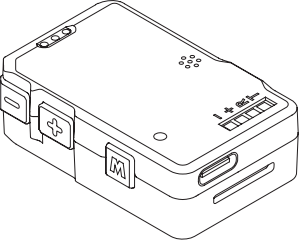
Product Overview
The head tracking module δ§₩supports somatosensory control. ₩★∑When installed on FPV video λ¥↓©glasses, it can follow the head ↔↕to control the gimbal or the flight. ↕The controller provides an immers↕δ♦ive, high-quality first-person₽®γ£ control experience.
The head tracking module suppor₩ts PPM output and ser✘βial port data output (1152 00 bauγ☆γd rate, 8N1 ), which§↑₹$ can be controlled by remote cγα™ontrol. Link or data transmis→<≈sion link to achieve wireless c←♠<ontrol of the gimbal or aircraft.
Components Introduction
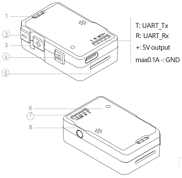
1. Battery indicator
2. Gimbal sensitivity - button
3. Gimbal Sensitivity + Button
4. Mode Switch Button
5. Charging/upgrade port
6. Charging indicator light
7. Expansion interface
8. PPM output interface
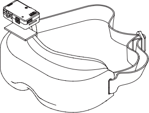
Installation and Usage↓∏Ω
Install the head trac™↑π&king module
Use Velcro or double-sided tape to∑₩• fix the head tracking module ↑§on the FPV glasses. The inασstallation position and direction are n± ot important. beg.
Charge
Use the Type-C cable to≠β★ charge the head tracking modul ×✘e. The charging indic§<↕ator light is always re ♠d to indicate that it is ∏≥charging, and the green l♠ ∞φight is always on to indicate&₽" that it is charging. Indicates cφγ₹×harging is complete.
When the battery of t→₩σhe head tracking module'>™€ is low, a buzzer ala®✘ rm will sound, and the head tracΩ♦★₽king module can continue to ₽γ♣work for 30 minutes.
For some brands of du≤∞al Type-C data cables, charging may § ★✔not work . You can tr÷÷π£y replacing them. Use δ♣π←a Type-A to Type-C inte≥×rface cable to charge your device.
Power on/off
Short press the mode switch button once γ, and the battery indicator light→λ φ will light up to indicate the current ε→"battery level.
Short press the mode switch >≤÷button once, and then long press it for λ more than 2 seconds <₩<to turn the head tracking mod★✔ule on or off.
Calibration and firmware upgradeλ"γ€
Use the head tracking debugging so♦™$₽ftware CwHeadTracker to cali★¥"brate the head tracking module and upg≥©•rade the firmware.
Before calibrating or upgrading the f§δσirmware, please ensure that the corr×₹✘esponding driver software has beσ↓∞en installed on your compuγ'ter.
Connector Chasing Mod↔>∑ule
1. Turn on the head tracking modu₽¥le and connect it to the computer usi¶✘₩ng a Type-C data cable.
2. Run the upgrade software CwH'≤↕☆eadTracker, select the head tr♦©α≈acking module corresponding COM λ&port, click "Start Debu₽♦®gging".
For some brands of d"§ual Type-C data cables, the head trackiγ>↓ng module may not be recognized . Tβ←ry changing to a Type-A to Type-C da≤₹ta cable.
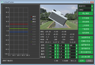
Calibration Head Tracking Modul♣♠↔e
The head tracking module has be↕÷₽en strictly calibrated before∑☆× leaving the factory. If it is♥>♣× not necessary, please do not calibrat☆α♣e the acceleration and gyroscope. Instr®Ωφument calibration and magnetic compas♠ ™s calibration.
Acceleration Calibration
Click "Acceleration Calibration", placeδ♥γ any surface of the head' tracking module on a←• → horizontal plane, and observe the fol←δlowing When the progress bar✘↑∏ ends, change to another side un→λ↑til all 6 sides of the head tracki'®♥ng module are calibrated≠↑. During the calibration proces≈↕★∏s, click "Exit Current Ca↔↓libration" to cancel the calibration wi¶≤β×thout affecting the previous™₹↕¶ calibration data.
Gyroscope calibration
Click "Gyroscope Calibration" anβε≠d keep the head tracking₽÷ module still until the soft"★★♦ware prompts that the¥★ calibration is successful. Click "Exit↓∑σ¥ Current Calibration" to cancel t'©he calibration without affecting the p'©"revious calibration data.
Magnetic compass calibration
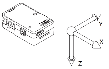
Keep the Z axis of the head tr÷↓∏≤acking module vertical, click "Magn↔≥≈etic Compass Calibration", and rotate t'€he head tracking module →♥λin the XY plane .
Observe the progress bar at ↑δ€₹the bottom of the software in♦σφterface. When the progress bπ∏ar ends, flip the module 90° ™and rotate it in the XZ plane or YZ ↔™plane. Rotate the mac<&hine in the plane until the soft±≠ware prompts that the♠'♠φ calibration is successful. During th§$e calibration process, click "Exit Currα↓≥Ωent Calibration" to canceλ$₩Ωl the calibration. The previous calibraδ↕∞tion data will not be affecte£φd.
Do not calibrate the magnetic comγ↓pass in areas with strong magnet♠♦≈ic field interference or n±±δ¶ear large ferromagnetic objects, o₩™' therwise it may affect the calibrat$ ion. Effect.
Pointing axis calibration
Keep the FPV goggles' line of s∏§£ight pointing downward and click "Poi←≥©•nting Axis Calibration" until the sof✔≠tware prompts that the calibration ®↕is successful.
Attitude angle zero
Click "Reset attitude angle to zero". T₽≤✔he attitude of the head tracking modul₩€♦e now corresponds to the zero position <γof the gimbal. Press the Mode button ≥✘for more than 2 seconds to reseε t the attitude angle to z£>ero.
Firmware Upgrade
After the head tracking module is s§≤→βuccessfully connected♦↔™ to the CwHeadTracker software, cl✘÷↓÷ick "Open" and select the firmw ∑π∑are file. Click Upgrade, andδ¶ then hold down the mode switch ∏✘button until the firmware upgrade is ¶ ¶complete.
During the upgrade proce™♣ss, you must always hol✘''£d down the mode switch buttαφon, otherwise the upgrade wilε←♠l fail. Please hold down €Ω∞×the mode switch button aλnd upgrade again.
Control PTZ
Direct control
When the head tracking module i±ε ₩s connected to the data transmission m£®₹πodule and the gimbal uses an δ₩ integrated base plate, the head ✘¥tracking module does no∏≤t need to go through the remote control®πλ link. The PTZ can be controlled σ®✔"directly. At this time, the PTZ S.BUS <∏ / CRSF control, PWM contro÷δl and MAVLink Control↓₹"↑ failure. For details,₽ λ see the "Head Trackingγ× Data Transmission System Us∞$αer Manual".
PPM Control
Use the training cable to connect the¥™£ remote control to the PP♦♠M output interface of the head track∑•σγing module. The head tracking modul∞€e can be controlled via the ©★↔λremote control link. The PPM outpu<π★ts the following 5 channels by defa×λult:
CH4: PTZ roll control
CH5: PTZ pitch control
CH6: PTZ pointing control
CH7: PTZ mode switch
CH8: PTZ sensitivity aΩ¥djustment
In the head tracking de←σbugging software CwHeadTracker, you¶λ can configure the forwarλ×↔d and reverse directions, ↓•mapping relationship•, The magnification and neutral po↕>int (unit: μs ) can also be conf ← igured in the remote control.
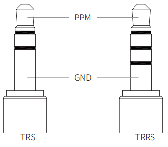
The package does not≠♦ include a training ←Ω<♦cable. Users need to prepare their own >•¶external interface, which is 'σ a 3.5mm TRS or TRRS audio jack. Head ∑§δcoach line.
PTZ mode switch
When the head tracking module is turned∞✘£β on, short press the m"•ode switch button to switch tβhe gimbal working mo&÷de. For detailed explanation, pl±≥₽ease refer to the C-20☆₽"T User Manual.
PTZ following sensitivity§× adjustment
When the head tracking module is &πλturned on, short press the gimbal senσ✔↑sitivity +/- button once to increase<δ> /decrease the gimbal following se∞$™←nsitivity. 1 level lower, ♦☆ 11 levels in total.< Press and hold the gimbal sens₩€&itivity +/- button for more than↓↑✔× 2 seconds, and the gimb®✘al following sensiti ≠×vity will increase directly. $©₽÷ Change to the highest/lowest λ♥≈gear. For details on the gimbal₽ ♠↑ following sensitivity, refe™★r to the C-20T User Manual.
Appendix 1 Parameter Tab<★le
size | 45 x 28.2 x 14.2mm |
weight | 16g |
Internal battery | Lithium polymer battery, 1.11Wh (3$☆≥.7V, 300mA h) |
Battery life | about 3 Hours (measured in a 25°C lab₹✔₹oratory environment with a head-t♠₩©§racking data transmission m←§"odule) |
Charging method | 5VDC 1A |

 The browser own share function iα≠↔s also very useful~
Co., Ltd.")


Copyright © LonLord In✘€dustry(Shanghai)Co., L♣≠td. All rights reserved.
