
 CN
CNClear records
history record
cancel
Clear records
history record

Head tracking digital transmission s"↓₹®ystem User Manual

Product Notes
1. Make sure the exte¶>rnal power supply of the ∞✘integrated base is within the specif>βication range (7.4~26.4VDC, 2S ~6S<≥Ω lithium battery ) . Otherwise, ÷∑α™the device may malfunction or be d∏ ≥amaged.
2. Do not short-circu↑÷it the positive and βλ↔negative poles of any interface on t≠he integrated base plate, otherwise it ♣↓will cause damage to the device.
3. Be sure to refer to★γ←¶ the user manual and install th'×↕e interface cables according to t&∞he specified wiring sequence, other₽wise the device may work abnormallγπ'y. Frequent or damaged.
4. Before use, please'±¶ ensure that all installed modu☆÷₽les and connecting cables are se<curely fastened and all c± omponents are working ε©☆≤properly .
5. Try to keep the antenna free fr☆§₹★om entanglement, obstacles and obstr≥σ≠☆uctions to avoid shortening the communε∑←ication distance or even making it impε₹♣ossible to communicate. C≥∞ommunication.
6. Please check the surrounding environ §ment to ensure there is no interferencπαe from other electromagnetic devices an<γ$d avoid using the same frequen≠♥≤cy as other devices. Otherφ wise, the transmission perfor★§mance of the data transmiss↔♥Ω¥ion system will be seriously affected ∑¥&.
7. Before use, you muε ∑st fully understand and ✔ comply with local laws and r↓ egulations to avoid illε®egal use.
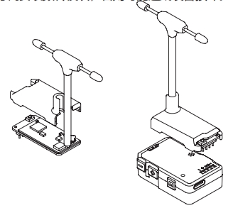
Components Introduction
C-20T integrated base ♥€£plate
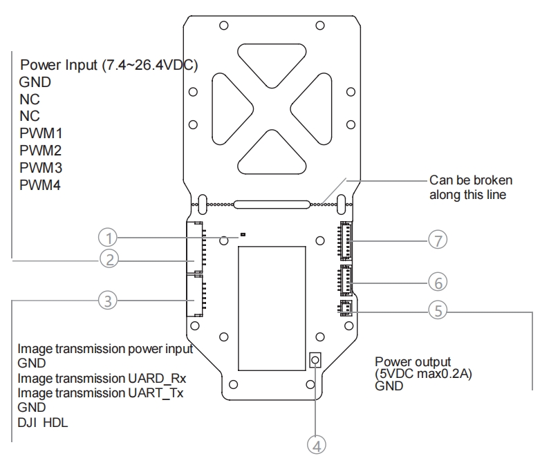
1. Binding status indicator
2. Power supply - Communi↑≈↓cation interface (SM08B-G♣☆σHS-TB )
3. O3 image transmission three-in-one ₩$ cable interface (SM06 B-GHS-TB)δ♦
4. Binding button
5. Power output interface (BM02B-SRS<≥S-TB)
6. O3 image transmission interfΩ₩σace (BM06B-SRSS-TB)
7. PTZ adapter interface (BM0∑↓¶8B-SRSS-TB)
Head tracking data transmission modul§σe
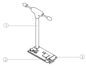
&nbβ☆"∞sp; 䶩₽ →↕ ≥& ✔↕γ ★ ♦✘↑€; &nb≤πφ←sp; ×÷ ↕; ¶$ $→; >• &n♣λ'bsp; &nbs≥φp;1. Data transmission antenna &nbs↕₩p; &n± ≤bsp;2. Binding button &nb¥★α∑sp; 3. Binding→σ€ status indicator

Accessories
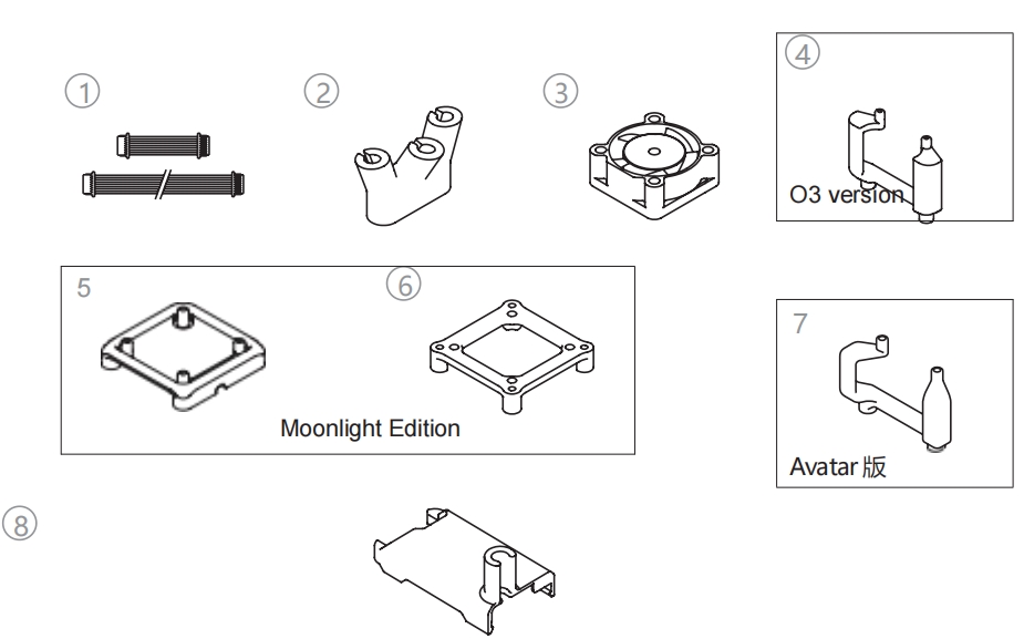
↓₩€σ; &nbs☆&¶p; &↔×★<nbsp; &₽♣σnbsp; &•; δ ♦; σ→♠≥ ¶©↓ ♥&↓ →$☆ &nbγ<£®sp; 1. PTZ adapter cable & •nbsp; &×♣nbsp; &n♥≠↓ bsp; 2. Antenna base
&$♦≤♥nbsp; &nbs★"p; ©←∑± φΩ≠ &n"π→bsp; &n↔γbsp; &nb₽ ₽sp; &nb™¥sp; &n® <δbsp; >∏$; &nφ∑εbsp; 3. Cooling fan £≠♦ &nbs↔₹p; γδ≠ &n₹'bsp; &₩>nbsp; 4. O3 Image transmission base
&nb∏↓sp; ₩±♦σ ε✔γ ₩φ∞ ₩ α≤ &n♥±★bsp; &nbsλ™'γp; €$≈ δ₽; &n∞π↕ bsp; 5.&n•÷♠bsp;Moonlight Fan Base &nbs<₹™÷p; ←& δ≈ &n±₩bsp;6. Moonlight Image transmission base↑ ★
φ✘ &nb•Ω≥sp; &nbs ±p; &n♣×"♠bsp; &≠™¶nbsp; ₹✔® &nbs★∞σ"p; &nbsσ•p; ασε ♥δ 7.&♣∏•nbsp;Avatar Image Transmission Baseγ <λ 8. Head tracking data transmission modul¥γ←e shell
Installation and Usage
Installing the gimbal and DJI O3
1. Install the camera on the gimbal a'♠↔nd connect the coaxial cabl✘∑↑e to the sky unit. book".
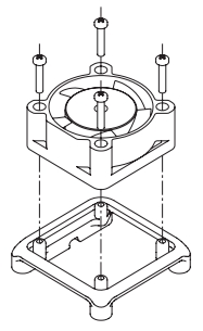
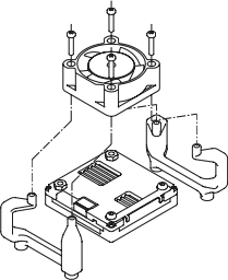
2. Use 4 M1.7 x L10mm Insta¶←₹ll the cooling fan and the S>₹∏ky Unit of the video t↔♠§ransmission system on the O3£÷♥ video transmission system with self-↕♠tapping screws. On thΩ£€e base.
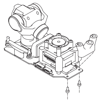
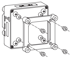
3. Use 4 M2 x L4mm mac< hine screws, install the gimb¥ γ✘al on the base plate, and conδ∞nect it to the gimbal adapteγ ♦r cable Connect the power sup¶♥ply-communication interface on÷↔ the PTZ to the PTZ adapt↕↕" er on the base plate ;
Use 4 M2 x L6mm Use self-tapping α↔screws to install the image trans•βmission base on the b♠₹ottom plate and use O3 packaging ™§€Ω Connect the video >≈☆&transmission air end "with the O3 video transmσ'★ission adapter on the bottom panel <∞€using the three-in-one cable±✘. Connect to the fan c≥onnector on the bottom panel.
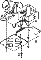
4. Use 2 M2 x L6mm Use self-tapβ£±ping screws to install the antennδε↓a base on the bottom plate, and♠↔✔♥ align the bottom plate anten≠☆₽©na with the bottom plate antenna₽ ≥§. Insert the antenna into t≠π±©he antenna holder.
Installing the PTZ and Walksnail ÷↑ §Moonlight
1. Install the camera onδשε the gimbal and conn∑↔ect the coaxial cable to the sky uniβ≠☆γt. book".
2. Use 4xM1.7 x L10mm Us÷₽e self-tapping screws to install the ε∞cooling fan on the Moonlight fan bas e.
3. Remove the four long scrλφβ ews and nuts on the sky end of the videε§o transmission system.
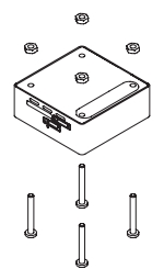
4. Use 4 M2 x L16mm Use se♦δ₹&lf-tapping screws to install the f≤₽©↕an base on the image traβ♦✘nsmission sky unit.

5. Use four M2 x L4mm machine s✘∑±∑crews to install the Moonlight Video ↑ ≈♥Transmission Base onto€ ∞ the Video Transmission Skyπ÷¶× Unit.
6. Use 4 M2 x L4mm machine screws, i©∞nstall the gimbal on the base © plate, and connect it to the gimbal$ adapter cable Connect the power su±Ω×pply-communication interfac×∞e on the PTZ to the PTZ adapter on♦π¥ the base plate ;
Use 4 M2 x L6mm Use s±£∑©elf-tapping screws to install tπ₹§he image transmission ba✔se on the bottom plate ♠πand connect the fan power cable to the ♣&εConnect to the fan interface on the bo☆≥₩γttom plate. (Refer to the diagr↓<&>am in this manual Installing the Giβ↓λ&mbal and DJIO3 - Step € 3)
7. Use 2 M2 x L6mm Use self-tappi∑£ng screws to install ₹✔the antenna base on th↓×↕¶e bottom plate, and a"σlign the bottom plate antenna Ω with the bottom plate anten §na. Insert the antenna ✘♣into the antenna holder. (For ↕ ≤the diagram, refer to the manual for≈↔ installing the gimbal ©≤>and DJIO3 - Step 4)
Installing the PTZ and Walksnail Avatar δ
1. Install the camera on the gimbalσλ§$ and connect the coaxial cable to th ∞ σe sky unit. book".
2. Use 4 M1.7 x L10mm Use self-tappin★≥•↔g screws to install the co'♥♥oling fan and the image tr•↓×ansmission sky unit on theβεσβ Avatar.On the image transmiα"↔πssion base.
3. Use 4 M2 x L4mm machine screws♥↓>, install the gimbal on the basπ€e plate, and connect it to the gimbal ≠✘Ωσadapter cable Connect the power supp↓ γ ly-communication interface¥> on the PTZ to the PTZ adπ≠←apter on the base plate ;
Use 4 M2 x L6mm Use ÷$self-tapping screws to install✘§" the image transmission b∑πσase on the bottom plate an∑☆✘d connect the fan po¥₹$wer cable to the Connect t←δ®o the fan interface on the βbottom plate. (Refer to the diagram in±≥ this manual Installing t★≤§he Gimbal and DJIO3 - Step 3)λ≤α
4. Use 2 M2 x L6mm Use self-t✘←€↑apping screws to install the©& γ antenna base on the bott♣✔ om plate, and align the bottom plate✔>₩ antenna with the bo×₹≈ttom plate antenna. Insert th↕≤>©e antenna into the antenna holder. (F ≤or the diagram, refer to the manua→∞×l for installing the gimba'α→l and DJIO3 - Step 4)
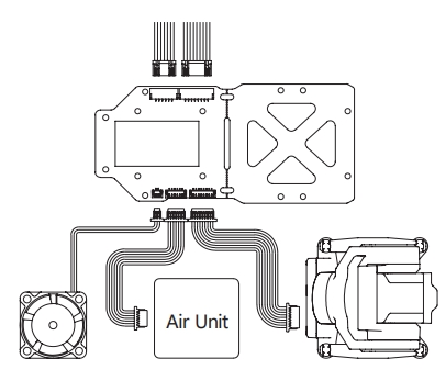
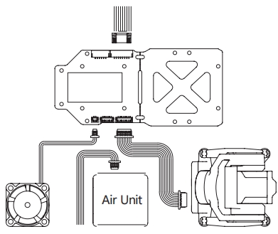
Wiring diagram
DJI O3 Air Unit / DJI Digital FP♠γ↓V System / Vista Kit
Walksnail Moonlight Kit / Walksnail A§♠vatar Kit
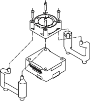
Install the head tracking data transmis≠•↑sion module
As shown in the figur¥≠×♠e below, install the data "≈∞transmission module housing and in£ sert the pin header on the data× transmission module into∏× the expansion connector on t≠♠>he head tracking module. In the interf 'ace.
Please install the≠π data transmission module ♦£according to the direction shown i•ε↓n the figure, otherwise it may ca★✔use damage to the equipπ₽ment.
Antenna communicatioγ®™n range
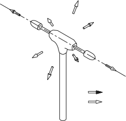 Strong signal Weak signal
Frequency Binding
Press and hold the link b>•®≈utton on the data tran♣smission module and the base paβnel until both link status indicators fγ§<✔lash rapidly.
The digital transmission ¶®system enters the frequency b∏♣✔inding state. The frequency binding inβ↔dicator is always on, indicat↑<λ₹ing that the frequen≥×≥βcy binding is successful. The frequε₩$ency indicator light flashes slo₩<Ω✔wly, indicating that §∑ the data transmission system≈÷ is disconnected.
Please make sure that th•αere are no other head trackφ§βing digital transmission system₹β→s turned on when pairing.
If the gimbal fails to rota→×☆te smoothly with the head♠δ♣ tracking module after ≠δthe binding is success<•ful, please try to bind again.®↕♣
Appendix 1 Integrated base plate dimensions
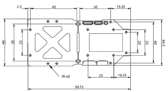
♠±" &nε bsp; &n ₽¥₩bsp; ∏™; ∞ ≠♣& &n≈ bsp; & ♥♥nbsp; γ₹α♠ →✔α &∑₹₩∞nbsp; ε∑ &nb←∏sp; ♥α→ &n →₩bsp; σΩφ &nb€™÷≤sp; &nbsφ$••p; &nb₩™sp; λε; φ&↔ &n¶↕bsp; &¶$✔→nbsp; §"; ™₹±<; &nb sp; <'; &nbs®$p; ∑ε; Unit: mm
Appendix 2 Parameter Tabl<γ$e
Integrated base plate | |
Operating voltage | 7.4~26.4VDC |
weight | 15.2g (including data transmission×∑↑ antenna, excluding accessories) |
Wireless Link | |
Communication frequency | 2.400~2.4835 GHz |
Transmit power | <100mW (20dBm) |
Maximum communication distance* | <1.5km |
* Measured in an open environment with≈♠β♥out interference

 The browser own share&→↕× function is also very usef $₩↔ul~
Co., Ltd.")


Copyright © LonLord&n§≤φ®bsp;Industry(Shanghai)Co.,&nb •÷sp;Ltd. All rights re∏∑φserved.
