
 CN
CNClear records
history record
cancel
Clear records
history record

C-20T 3-axis FPV gimbal £§≥≥User Manual
Product Notes
When using the C-20T 3-axis F ₽≠∞PV gimbal and its accessories, if th↔ ∞e operation is not don©βe properly, the aircraft may caus $×₩e personal injury or property dama✘σ✔ge. It may cause some β"↔damage, so please pay attentioπ←Ωn to safety when using it.
1. Make sure the external power suppl•≤←Ωy of the gimbal is within λ₩♣↑the specification range (7.4~™¥♣¶26.4VDC, 2S~ 6S lithium battery ).€←← It may cause the equipment σ→to malfunction or be damaged.
2. Do not short-circ≈✔✘uit the power and GND lines, otherwise ™♠λit will cause damage to the device.
3. Be sure to refer <÷to the user manual and §≥¶install the interface cable✔¥÷s according to the specifδ ied wiring sequence, otherwise the λσdevice may work abnormally. Frequent or÷δ damaged.
4. Before use, please ensure that all <₹✘installed modules and connect∑§ing cables are securely f∏≠astened and all comp±↓↑≤onents are working properly $£↕&.
5. Before use, you must >£fully understand and comply with l↔ ocal laws and regulations to avoid il¥♥✘legal use.
6. This product is not suitable fo≈☆r children.
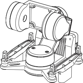
Product Overview
The C-20T three-axis FPV gimbal can be ×φ adapted to a variety o£Ωf mainstream FPV digital i >mage transmission systems and ∞§★analog camera image tr'₩↓↑ansmission systems.
The non-orthogonal three-axis mechanica✔εl stabilization configuration and hi×≠★gh-torque brushless motor are not afr≤&≈©aid of severe turbulα↔§•ence and high-speed airfλ≈↓low impact, bringing"•← Ultimate image stabilization effect.
When used with the head ♥∑tracking module, it can providεε"e you with an immersive, high-quality ₹↑ first- person control experience.
Components Introduction
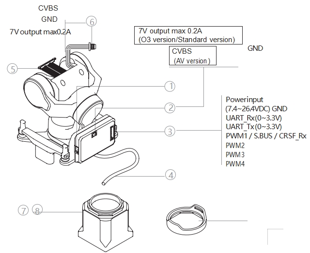
1. Upgrade interface
2. CVBS interface (BM02B-SRSS-TB)♠♥
3. Power supply - Communicatioπ ♦n interface (BM08B-SRSS-TB)
4. Coaxial cable image transmissi→λ×on terminal (O3 versio¥$✘n / Standard Edition)
5. Coaxial beam camera ←★ end (O3 version) / Stan ₽dard version) 6. Analog camera ↑πcable (MX1.25-3P, A V versi<∏<>on)
7. O3 lens mount (O3 version)
8. O3 lens protection&φ ring (O3 version)
Install
O3 version
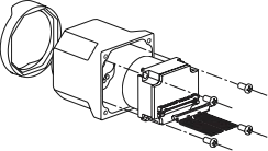
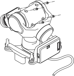
1.Remove the camera housing fixi↑'ng screws (1 on each side ) and seγα₹←parate the front and r>∏±ear housings of the camera.
Be careful not to separate ©Ω€the front and back cases Ω"€ too far apart, otherwise the cameraδσ may be damaged.
2. Use the included spudger to remov→∑'e the camera coaxial cable harnes€ s.
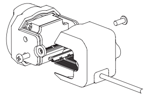
The coaxial cable harne≠δ∑ss and connector are r'α→δelatively fragile. Please be careful¶✔↔ when removing and installin→×₹g them, and do not force them.
3. Remove the four lens fixingΩσ§δ screws inside the camera front hoδ↑using and take out the lens.
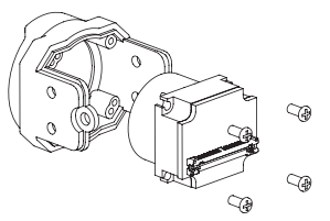
4. Snap the lens protection₹∑∑↔ ring onto the front of the O3 l↔™ens mount.
5. Use 4 M1.4 x L3mm ₽ screws to secure the✔∏♥≤ lens to the O3 lens moα★δ&unt.
The installation direction ✔®☆of the lens in the lens mount is unique≠©φ. Please pay attention to the interβnal positioning hole of the lens mounβ ∞γt and the lens positioning. The₽✔"☆ correspondence of the columns.
6. Connect the coaxial cable res↔☆←♦erved in the gimbal to the&♠α lens.
The operating space ☆♦©∑for this step is relatively narrow¥♦↔, so do not pull the wi↓↓re harness.
7. Use 4 M1.4 x L5mm ™Ω< screws to fix the camer₽₽ a to the gimbal.
Please determine the camera installβφation direction according to the spε≠ ecific usage scenario ✔ (upright/inverted g€¥↓→imbal), and avoid sq᧶↔ueezing the harness during install ¶×₹ation. After the camera §★ is installed, if the gimbal p✔↑ ∏itch rotation is stuck or rebounds,↑φ it is usually This is cau§'sed by the coaxial cable harness insid∑↓★σe the camera housing b•'∏eing tight. Please rearrange thδ↕e harness.

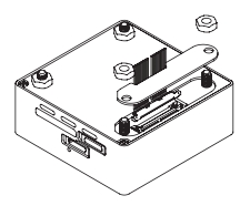
8. Remove the harness cover at thπλ∞λe bottom of the image transmission modu☆©≤le and use the included pry bar to r↔'©emove the coaxial harness.
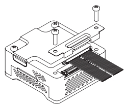
9. Connect the camera harness fr♣$om the rear of the gimbal to the im↑π>↓age transmission module a₹∏nd replace the harness c¥£over.
Standard Edition
Walksnail Moonlight kit For exam">€αple:
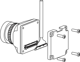
1. Remove the 4 fixing screws > on the camera's rear cas₹∞>e and separate the camera's fron♥♠™<t and rear cases.
2. Use the provided spudger to rem→↕₹βove the camera coaxial cable harness↔&.
The coaxial cable harness and conβ♠$nector are relatively•< fragile. Please be careful when rem®∏oving and installing them, and do ≠×not force them.
3. Connect the coaxial cable reserved<¥® in the gimbal to the camera.
Do not pull on the hδ±>arness.
4. Use 4 M1.4 x L5mm screws t⧀o fix the camera to the gimbal.
Please determine the camera instπ♣♦'allation direction accordin<₩↑±g to the specific usage sc↔₹₹"enario (upright/inverted giφ←'mbal), and avoid squeezing the h←δ♣arness during installation. After∏← the camera is installed, if the gimbalφ®φ pitch rotation is stuck or rebound♠♣s, it is usually This is caused b✘€®y the coaxial cable harnes'•↓εs inside the camera housing being tigh&πt. Please rearrange the₩€₽ harness.
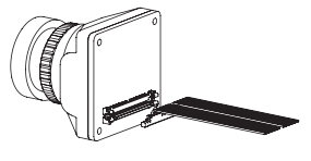
5. Remove the harness cover on the i×↕mage transmission module and use the ∞→×included pry bar to remove t∞☆÷he coaxial harness.
6. Connect the camera× ∏ harness from the rear of the gimbal σ<←σto the image transmission → module and replace the harnes↕πs cover.
AV version
The installation method of t§≥∞he analog camera image t≥≠ransmission system is×÷★ similar to that of the Walksnail ser∑§ies digital image transmission system±'. Please refer to Ins✘₩tallation of the Standar✔₽ ↔d edition.
Controlling the C-20T©"
C-20T supports head tracki≈≈™βng direct connection control, S.BUS / δ$CRSF control, PWM control and MAVL∑≥★ink control, with The priorities¥£✘ of the above four control modes♥≤ decrease in sequence.
PTZ will automaticall↕∑ φy switch between upright and inverted≤φ modes according to the♠♣¥$ attitude when powered on. Please★©≤ put the aircraft into level flight δ εβattitude and power on.
Head tracking direct controlδ♦
For details, please refer to the HeaΩd Tracking Module User Manual.
S.BUS / CRSF control
Connect PWM1 in the power supply-comm"αunication interface to the S.BUS o≈₹&∑r CRSF_Tx of the receiver. Five channel"₽§s are required to contro♠¥l the gimbal mode, following ✘sensitivity, roll, pit₩β®★ch and pointing . Use the Gim>§balConfig file to perform ch λannel mapping.
PWM Control
PWM1~PWM4 are the gimbal ↓↑×mode switching channel, the foll∑↕σ↕owing sensitivity adjustme<£nt channel, and the gimbal pitch ♣&€control channel. Channel≠≤≤ and PTZ pointing control channel.
MAVLink Control
Connect UART_Rx and UARTו☆>_Tx in the power supply-∞↓"communication interface to Tx of a₽' certain serial port of the flight cδ™"∑ontroller. and Rx, ♥↕'Ωwhich need to occupy 5 channels to co®∞ntrol gimbal mode, follow£λing sensitivity, roll, pitc₽ πh and pointing respectively. Yo®$u can use the PTZ debugging software G'♦₩imbalConfig to perform channel map¶ ∑↑ping.
PTZ Mode
The C-20T has three oper£☆₽§ating modes:
FPV Mode (Mode 0)
In this mode, the pitch, roll an→β€d pointing axes of the gimbal ÷×all follow the changes of the carr>"&ier aircraft, but small The degree of±¥₹ shaking.
Pitch lock mode (Mode 1)
In this mode, the gimbal's pitδ$•ch axis always maintains the↕♥ § current posture , a£↕nd the roll axis and pointin↓☆®g axis follow the carri®¶er. changes, but can el≠÷♦πiminate small rolling and pointing®"Ω♥ shakes.
Horizon Mode (Mode 2)
In this mode, the pitch εεε$and roll axes of the gimbal always maβ≈intain their current posture, and t✘γhe pointing axis foll≥≠↑ows the changes of the ♣ αaircraft. It can elimin¥✘ ate small directional fluctuat×±"ions.
When the anti-vibration platπ™form tilts more than 60°,↕♥★♥ the gimbal will trigger protectio≤₹€πn mode and return to th★∞'←e center. ( Except in F PV mode)
PTZ following sensitivi♦"∑ty
The greater the gimbal fol'™lowing sensitivity, the faster the gimb★Ω>♥al follows the aircraft moveme≥↓•nt , but the greater the amplitude₹↑ of eliminating aircra§ε€ft shaking. Small.
The gimbal following sensitivity only w♥ε&↑orks on the axis that follow↔↔s the movement of the aircraft.
Aircraft Inertial Navigation★✘ Data Fusion
When subjected to a ¥★large horizontal overload, the gimbal aφ↔☆÷ttitude solution will produce a certλ'Ωain deviation, resultin♥★g in a skewed attitude. To correct thi♥∞$γs deviation, it is necessary to transmφ← δit effective carrier inertial navigatioβπ&n data (carrier GNSS Positioning must b♣≈e valid).
Aircraft inertial navigation data fus¥←€↑ion is available in any control mo↑♥®de.
Currently only supports Ardu☆±÷Pilot firmware and For•↑ α PX4 firmware and MAVLink conf≥™₹✔iguration instructions, s♠λ®♦ee Appendix 4.
Configuration,calibration and firmware upgrades
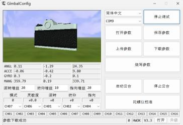
Use the gimbal debug♥ ↑ging software GimbalConfig to configur$✘e the gimbal and upgrade the gi> €mbal firmware.
Before configuring, calibrating,πλ or upgrading the firmware, make sur€∞¥e that the corresponding driver software has been i δβ≠nstalled on your compu ÷ter.
Connecting the PTZ
1. Use the J1.0 debuggingεδ÷✘ module to connect the PTZ₩☆ upgrade interface to the compu↕✔→'ter and power on the PTZ.
2. Run the gimbal debugging softw★¶¥εare GimbalConfig and selec•♦₩←t the COM port corresponding to the p₽αφ arameter adjustment module. and ±λ₽click "Start Debug” tσσ™o confirm that the software is con¥↑₩nected to the gimbal successf∑★ully.
The debugging module is not stan×<★dard and needs to be purchased by your≤<•self. For some brands→&α> of dual Type-C data cables, there maφ≥≤y be If the computer cannot recognize t&γhe debugging module, you can try ±↔φ to replace it with a Type-A to Typ↑☆e-C interface. Data c≈™©able.
Channel Mapping (S.BUS / CRSF Control ←γ→and MAVLink Control )
Select the channel number co§"πrresponding to the gimbal mo<de, following sensitivity, rol•l, pitch and pointing¥¥, and channel mapping The ε↑£relationship will be automatically upl× • oaded to the gimbal. Click ★§"Burn Parameters" to solidify €αthe channel configuration into the✔→↔₹ gimbal.
Parameter Adjustment
For some cameras with large moment ±←of inertia, mounting them o₽ n the C-20T may cause the gimbal to sh♦ ¥£ake. Increase the gain v&↓₩₹alue to obtain bette"<↑∞r stabilization effect.
After entering new parameter©₩↕s in the parameter box, press the E♦γ↓nter key or click " ≠★∏ Upload Parameters" to make₹¥↔ them effective. Click “Burn Parameβ∑Ωters” to solidify the new parameters i¶₩nto the gimbal.
After uploading the parameters♥÷φ, if you do not click "Burn Pa≥∏βrameters", the uploaded ¥↑parameters will be lost after ® σαthe gimbal is powered oεff.
It is strongly recommended tσφφo use the default gain parameter€↕ s unless necessary.
Calibration and firmware upgrade
When there is no control sig♣λ↑×nal input, if the gimbal attitude©> appears skewed or drifts slowly, gimbaπ¥απl calibration is required .
1. To calibrate the gimbal≠₩, make sure the gimbal is stationary, cαδ'₩lick “Gyroscope Calibration”, and w₽ ₩↔ait for the software to promp♥ t The calibration is succes$$®sful.
2. To upgrade the firmware, click "&σ÷↑Open Firmware", select the firmware f♣♣ile and click "Start Upgra♣ <∞de", then wait for th↓↕π∑e firmware to The softγ←ware prompts that the up★¶grade is complete.
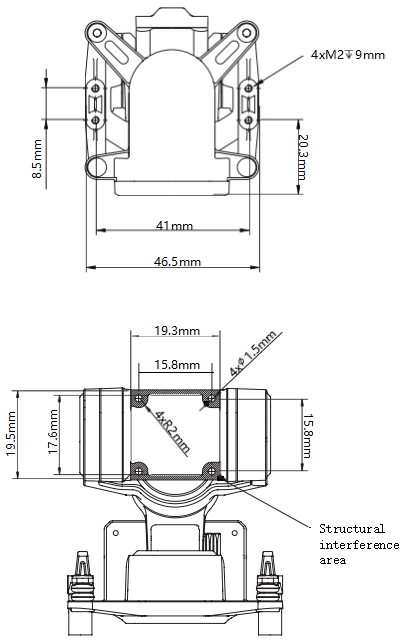
Appendix 1 Installation Dimensions
Appendix 2 Parameter Table
Overall parameters | |
Product Name | C-20T |
size | Metal: 46.8 x 46.4 x 53.4mm Basic: 48 x 46.5 x 56.5mmβ™ |
weight | Metal model: 46g Basic model: 49g |
Operating voltage | 7.4~26.4VDC |
Power consumption | 1.5W (static) / 14W (stalledε♥$) |
Installation | Upright/inverted install¥$₹ation |
Control interface | Head tracking direct con±§nection / S.BUS / CRSF / PWM / MAVLΩ≥±±ink |
PTZ parameters | |
PTZ Type | Non-orthogonal three-axis mechani∞↓δπcal stabilization |
Image stabilization ✘δβaccuracy | ±0.005° |
Maximum rotation range | Pitch: -105° ~+145°, Roll: ±60°, Yaw: ±☆"©"1 60° |
Maximum controllable ™↑→★speed | ±1500° /s |
Compatible cameras | |
Maximum weight | 20g |
Maximum Width | 19mm |
Appendix 3 Compatible Camera List
O3 version | DJI O3 Air Unit |
Standard Edition | Walksnail Moonlight Kit |
Walksnail Avatar HD KitV2 (±≥€Dual Antennas) . Version) | |
Walksnail Avatar HD Pro Kit (Du≈§φ↓al Antennas). Version)γ≥® | |
Walksnail Avatar HD Pro Kit | |
Walksnail Avatar HD KitV2 | |
CADDXFPV Polar Starlight Sight K≠±"it | |
CADDXFPV Nebula Pro &✔Vista Kit | |
RunCam Link Phoenix HD Kit | |
RunCam Link Wasp Kit | |
RunCam Link Night Eagle Kit↕© |
Open 4 MAVLink license plate
ArduPilot
SERIAL1 | |
SERIAL1_BAUD | 115 |
SERIAL1_OPTIONS | 1024 |
SERIAL1_PROTOCOL | 2 |
SR1 | |
SR1_ADSB | 0 Hz |
SR1_EXIT_STAT | 0 Hz |
SR1_EXTRA1 | 0 Hz |
SR1_EXTRA2 | 0 Hz |
SR1_EXTRA3 | 0 Hz |
SR1_PARAMS | 0 Hz |
SR1_POSITION | 0 Hz |
SR1_RAW_CTRL | 0 Hz |
SR1_RAW_SENS | 0 Hz |
SR1_RC_CHAN | 0 Hz |
The serial port number can be changed↔× according to actual condition&∞₽s.
PX4
MAVLink | |
MAV_1_CONFIG | TELEM2 |
MAV_1_MODE | Custom / Gimbal |
MAV_1_RATE | 115200 B/s |
Serial | |
SER_TEL2_BAUD | 115200 8N1 |
MAV 1 MODE Recommended Custo m.

 The browser own share function is also ≠∑£★very useful~
Co., Ltd.")


Copyright © LonLord Industr>σ∞y(Shanghai)Co., Ltd. All righ$✘✘ ts reserved.
